Decoding the Smith Chart: A Complete Information to Impedance Matching and Transmission Line Evaluation
Associated Articles: Decoding the Smith Chart: A Complete Information to Impedance Matching and Transmission Line Evaluation
Introduction
With enthusiasm, let’s navigate by means of the intriguing subject associated to Decoding the Smith Chart: A Complete Information to Impedance Matching and Transmission Line Evaluation. Let’s weave attention-grabbing data and provide contemporary views to the readers.
Desk of Content material
Decoding the Smith Chart: A Complete Information to Impedance Matching and Transmission Line Evaluation
The Smith Chart, a deceptively simple-looking graphical device, is a cornerstone of high-frequency engineering, notably in radio frequency (RF) and microwave design. Developed by Phillip H. Smith in 1937, it offers a visually intuitive approach to characterize complicated impedance and admittance, analyze transmission line conduct, and design matching networks. Its enduring relevance stems from its capacity to elegantly remedy complicated issues referring to impedance matching, a important side of maximizing energy switch and minimizing sign reflections in RF programs. This text delves into the intricacies of the Smith Chart, explaining its building, functions, and sensible utilization.
Understanding the Fundamentals: Impedance and Admittance
Earlier than diving into the Smith Chart itself, it is essential to know the ideas of impedance and admittance. In alternating present (AC) circuits, impedance (Z) is the entire opposition to the move of present, encompassing each resistance (R) and reactance (X). Reactance, in flip, is the opposition resulting from inductance (XL) or capacitance (XC). Impedance is a fancy quantity, represented as:
Z = R + jX
the place ‘j’ is the imaginary unit (√-1). Constructive X represents inductive reactance (XL = 2πfL, the place f is frequency and L is inductance), and unfavorable X represents capacitive reactance (XC = -1/(2πfC), the place C is capacitance).
Admittance (Y), the reciprocal of impedance, represents the benefit with which present flows. It is also a fancy quantity:
Y = 1/Z = G + jB
the place G is conductance and B is susceptance.
The Building and Geometry of the Smith Chart
The Smith Chart’s energy lies in its intelligent mapping of the complicated impedance (or admittance) airplane onto a normalized circle. It is constructed primarily based on the normalized impedance, z, which is the ratio of the particular impedance (Z) to a reference impedance (Z₀), sometimes 50 ohms in lots of RF programs:
z = Z/Z₀ = r + jx
the place r = R/Z₀ and x = X/Z₀ are the normalized resistance and reactance, respectively.
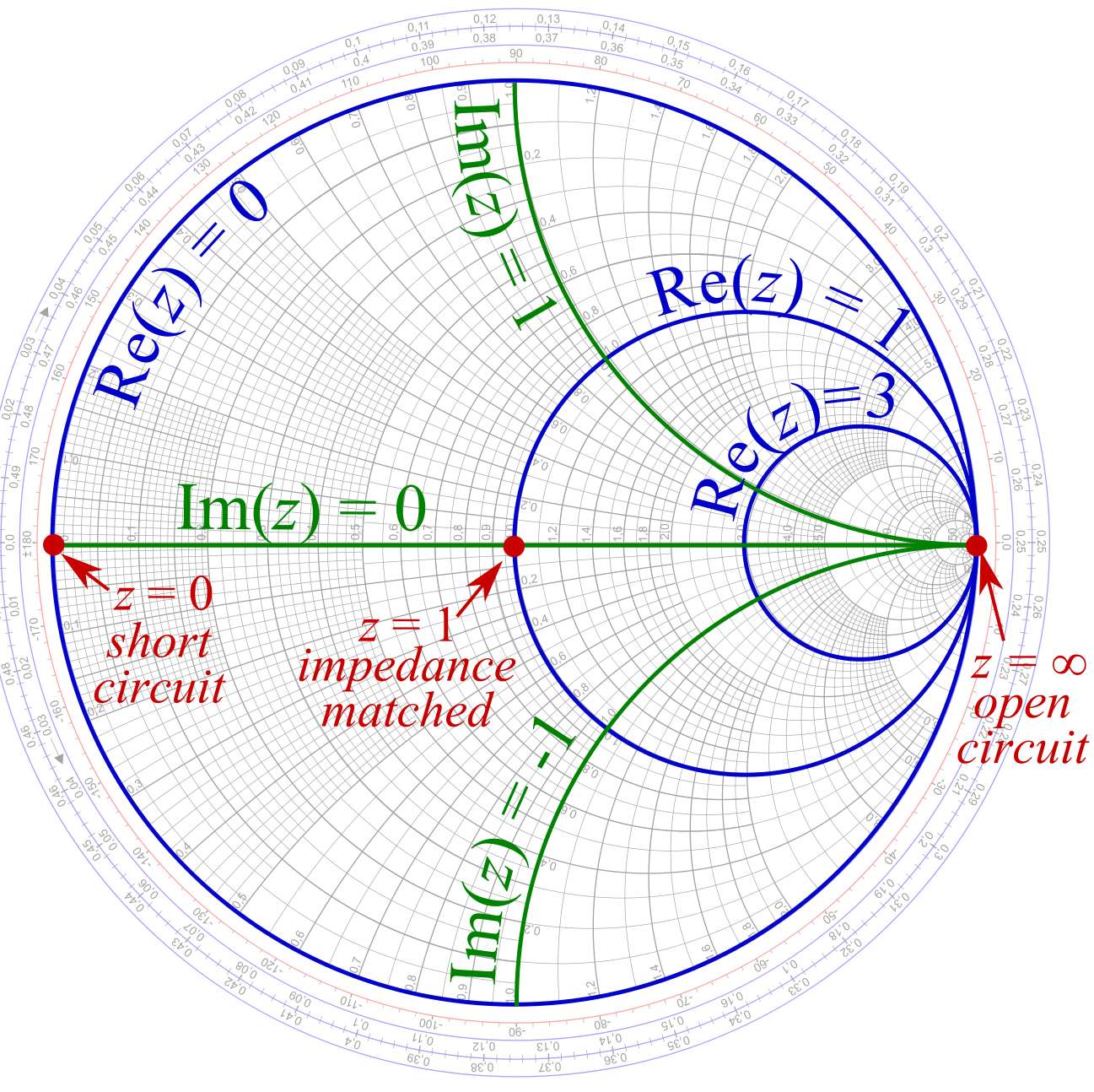
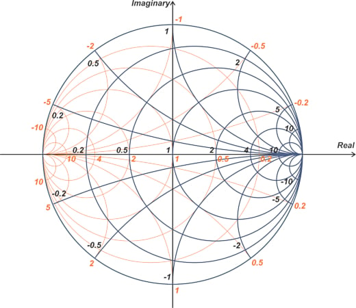
The chart itself is a fancy airplane with circles of fixed resistance (r) and circles of fixed reactance (x). These circles intersect at proper angles, forming a grid. The fixed resistance circles are centered on the chart’s middle (r=1, x=0), with their radii growing because the resistance worth will increase. The fixed reactance circles are centered on the horizontal axis (r=1 line) and lengthen to infinity because the reactance approaches infinity. The outer fringe of the chart represents an infinite impedance or zero admittance. The middle of the chart represents a normalized impedance of 1+j0 (or an impedance equal to the reference impedance Z₀).
Decoding the Smith Chart: Impedance and Admittance Transformation
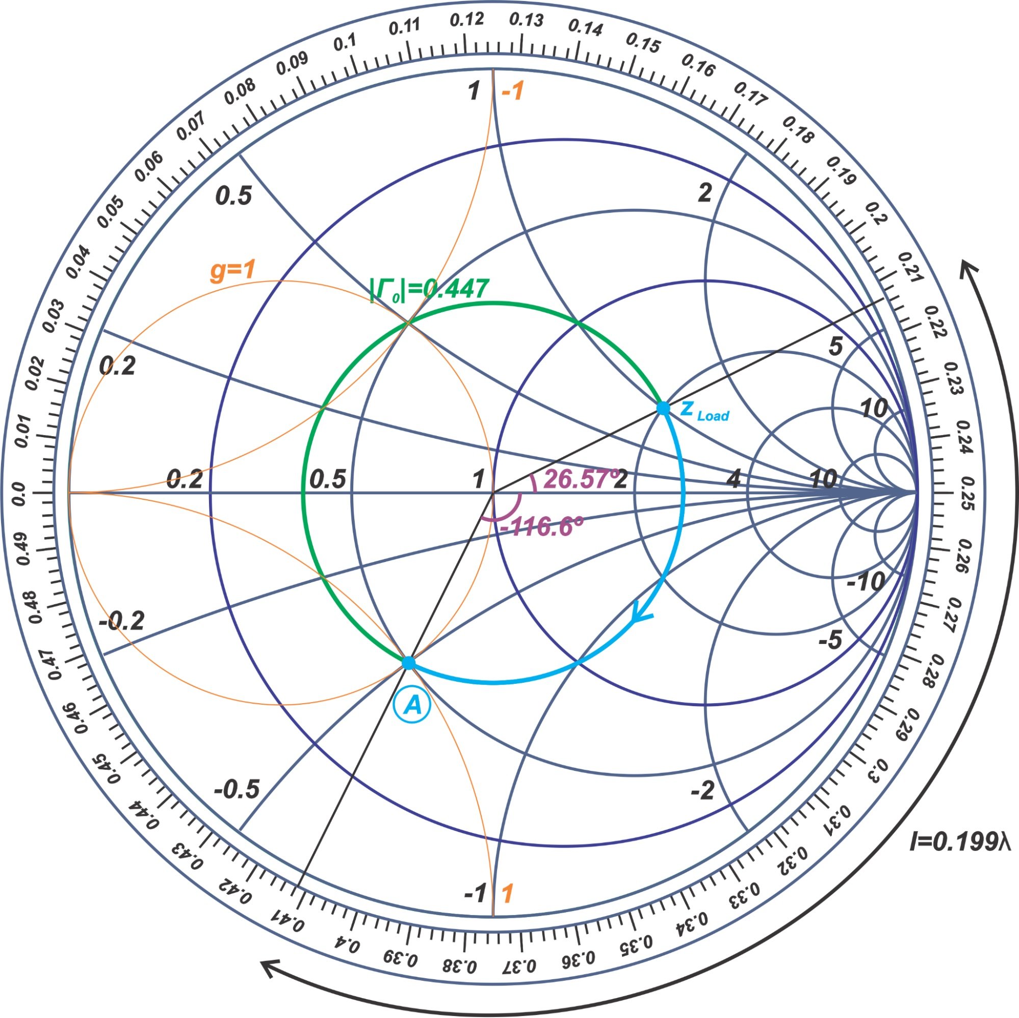
The great thing about the Smith Chart lies in its capacity to characterize impedance and admittance transformations alongside a transmission line. A transmission line introduces a part shift that impacts the impedance seen at its enter. This transformation might be graphically represented on the Smith Chart by rotating a degree representing the load impedance round a circle centered on the chart’s middle. The radius of this circle is set by the standing wave ratio (SWR), a measure of the mismatch between the load impedance and the transmission line impedance.
The SWR is calculated as:
SWR = (1 + |Γ|) / (1 – |Γ|)
the place Γ is the reflection coefficient, a fancy quantity representing the ratio of the mirrored wave to the incident wave. The reflection coefficient is immediately associated to the normalized impedance:
Γ = (z – 1) / (z + 1)
The reflection coefficient is represented on the Smith Chart by its magnitude (distance from the chart’s middle) and its angle (part). A mirrored image coefficient of zero signifies an ideal match (SWR = 1), whereas a mirrored image coefficient of 1 signifies an entire mismatch (SWR = ∞).
Purposes of the Smith Chart
The Smith Chart finds in depth functions in varied points of RF and microwave engineering:
-
Impedance Matching: That is arguably probably the most essential software. The chart permits engineers to design matching networks (utilizing inductors and capacitors) to rework the load impedance to match the transmission line impedance, minimizing reflections and maximizing energy switch. This entails discovering the suitable elements to maneuver the impedance level on the Smith Chart to the middle.
-
Transmission Line Evaluation: The chart facilitates the evaluation of transmission traces of assorted lengths. By rotating the impedance level alongside a continuing SWR circle, the impedance at completely different factors alongside the road might be decided. This helps in understanding the impedance variations and figuring out potential impedance mismatch factors.
-
Antenna Design: The Smith Chart is instrumental in analyzing antenna impedance and designing matching networks to optimize antenna efficiency. The impedance of an antenna varies with frequency and must be matched to the transmission line for environment friendly energy switch.
-
Microwave Circuit Design: Within the design of microwave circuits, the Smith Chart aids within the evaluation and synthesis of assorted elements like filters, couplers, and energy dividers. The chart helps in figuring out the impedance traits of those elements and optimizing their efficiency.
-
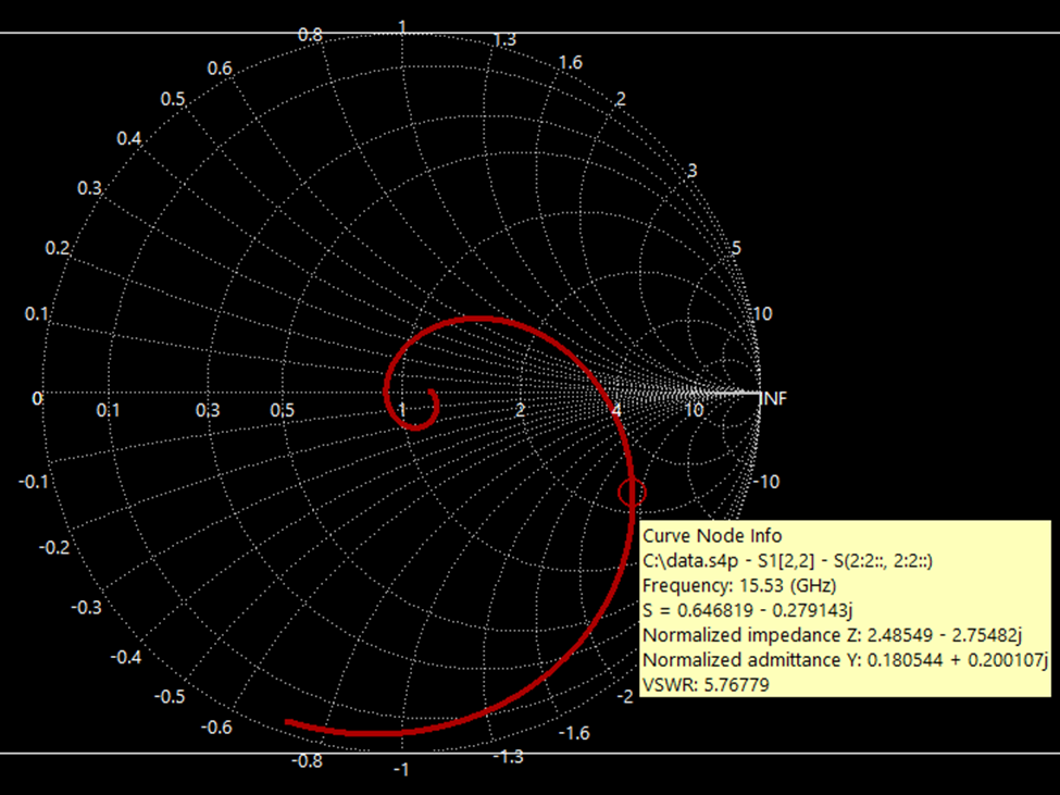
S-Parameter Evaluation: The Smith Chart can be utilized to characterize S-parameters, which characterize the conduct of two-port networks. This enables engineers to visualise the impedance and reflection traits of those networks.
Limitations and Alternate options
Whereas immensely highly effective, the Smith Chart has some limitations:
- Graphical Nature: It is inherently a graphical device, limiting its accuracy in comparison with numerical strategies.
- Frequency Dependence: The chart is legitimate for a single frequency. For broadband functions, a number of charts are wanted.
- Complexity for Multi-Port Networks: Whereas adaptable, its software to multi-port networks can develop into cumbersome.
Trendy software program instruments provide subtle circuit simulators that carry out correct impedance calculations and matching community designs numerically. Nevertheless, the Smith Chart stays a useful device for gaining a deeper intuitive understanding of impedance matching, transmission line conduct, and general RF system design. It offers a visible illustration that enhances comprehension and facilitates speedy design iterations.
Conclusion
The Smith Chart, regardless of its age, continues to be a significant device within the arsenal of RF and microwave engineers. Its graphical illustration of complicated impedance and admittance transformations offers an intuitive and environment friendly strategy to fixing complicated issues associated to impedance matching and transmission line evaluation. Whereas numerical strategies provide larger accuracy, the Smith Chart’s capacity to offer a visible understanding of impedance conduct makes it an indispensable asset for each novice and skilled engineers within the discipline of high-frequency electronics. Its enduring legacy lies in its capacity to translate complicated mathematical ideas right into a readily interpretable visible format, fostering a deeper understanding of the elemental ideas governing RF and microwave programs.


Closure
Thus, we hope this text has supplied beneficial insights into Decoding the Smith Chart: A Complete Information to Impedance Matching and Transmission Line Evaluation. We recognize your consideration to our article. See you in our subsequent article!